Cornish Hydrogen Generator
KeelyNet 01/10/02
US Patent 4,702,894 - Cornish - October 27, 1987
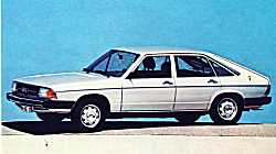
Your Car can run on water using this device without pollution !
Costs: 400 miles = 1 $. ( One US dollar ).
Copyright Layo France, Hyères,
Water Carborator : How
Your house can be warmed up this way .
Hardly a subject can be more important to humanity than the present one, . . .
A forgotten patent !
You will find here the exact transcript of the 30 June 1982 European patent Publication N° 0055134A1 allowing a car effectively running on water and little aluminum ( I Gk. at 1$ for 400 miles ) without any pollution whatsoever.
Inventor: Mr. Francois P. Cornish, UK
Last seen in Canada ( summer 1988 ). We are unable to locate him since several years now which is rather bothering.
If you (the reader) heard from him or know his place, please contact us or ask him to contact us.
Webmasters please do link this planet-saving information but do also mirror on your site ASAP - and refer to : www.layo.com (site no longer exists)
All photographs are our own making when visiting Mr. Cornish in London in 1983 and copyrighted.
Specifications:
Water is split into Hydrogen and Oxygen
Oxygen is cleverly combined with aluminum
Hydrogen is collected and sprayed in a standard carburetor like with methane-gas.
A 900 Kilo car runs 600 Kilometer on 20 liter water and 1 Kilo aluminum.
Clean energy, once put in Aluminum at 1$/Kg, refining Bauxite, is released here first
making oxygen inoffensive.
Why we don't see these cars yet ?
At the time (1981) only some minor difficulties existed (see the BMW letter).
Electronic control developments might make this easier to implement today. Please think about the following:
To develop a smooth way to get rid of the aluminum oxide powder from the bottom of the water reservoir.
Find an absolutely sure check signaling if oxygen remains although the BMW-letter is not speaking about that point.
Don't experiment if you are unqualified, . . .
remember combining O² and H² is highly dangerous - - -
Use oxygen sensors.
Engineers must attack this subject before this planet runs out of time !.
A Letter from BMW on the subject
BMW AG
Muenchen 40 Postfach 40040
References: 3895-5538
Nov 5, 1981
Proposal for improvement
Dear Mr. Cornish,
In reply to your telex of 17th October, our findings to date are as follows:
The unit as present assembled in a 2000cc car produced sufficient gas to power the engine continuously.
The aluminum consumption averaged out at 180 cm per minute over a 70 minute test run.
With the capacitor (as per your specification) connected up, we were able to work in our 14v environment.
The water temperature remained low, and even without the radiation system was found to be well between your limits.
No acid was found on analysis after the test run.
We however feel that one possible problem area may be the disposal of the oxide deposit. Could you please let us know what your findings have been on this side.
Yours faithfully,
Bayerische Motoren Werke Aktiengesellschaft
Service Division
I.V. Henseler
V. Krause
Here follows a complete text of this neglected
June, 30, 1982 European patent Publication N° 0055134A1
BACKGROUND OF THE INVENTION (text 8/8/96 OCR-scanned and partly corrected..)
This invention relates to hydrogen generation.
It has already been proposed to replace conventional fuels with hydrogen in the running of internal combustion engines. Conventional proposals are to produce hydrogen by the electrolysis of water and then to store the hydrogen in some form or another. No economically viable storage system for the highly explosive hydrogen gas has yet been evolved. Whatever system is evolved would involve fairly massive tanks of some kind or another and precautions to prevent explosions. The present invention is based on the desire of the inventor to be able to provide hydrogen on demand from materials which are in themselves safe to handle.
SUMMARY OF THE INVENTION . According to the invention a method of generating hydrogen comprises the steps of exposing a fresh metal surface to water and heating the interface between the metal surface and the water at least to the lowest temperature at which the metal reacts with water to form a metal oxide and hydrogen, the metal being chosen from metals which are higher in the electromotive series than hydrogen and having stable and safe handling characteristics. Preferably the metal surface is exposed and the interface heated by pressing an electrode of the relevant metal against a second electrode under water and applying a high voltage between the electrodes while preferably moving the electrode surfaces relatively to one another.
In other words in the preferred form of the invention hydrogen is formed by creating an underwater electrical discharge between two electrodes at least one of which is made of a metal as defined above.
The electrical discharge and the relative movement between the electrode surfaces ensure that fresh metal surfaces are exposed to the water while at the same time the discharge heats the interface between the electrodes and the water to the required temperature at which the metal reacts with water to form its oxide and to liberate hydrogen.
Also in the preferred form of the invention rile metal is aluminium which has the advantage that it is in relatively abundant supply relatively cheap is formed with a protective oxide layer on its exposed surfaces and reacts with water at a relatively low temperature. Aluminium wire fed against a rotating aluminium drum has been found to give excellent results to provide hydrogen for powering small internal combustion engines.
A convenient way of securing the high voltage required is to employ the conventional distributor and coil arrangement which provides the sparking for an internal combustion engine. Two coils in parallel fed from a common distributor has been found to give excellent results. Other methods of generating high voltages from the.comtery or the drive shaft of an internal combustion engine may also be used. The method of the invention lends itself in an excellent manner to supply hydrogen on demand. In this case hydrogen is fed to a small buffer store and as the pressure in the store exceeds a predetermined level, the electrodes are separated so that hydrogen generation is interrupted. As the pressure drops to a certain level the electrodes are again fed towards one another.
BRIEF DESCRIPTION OF THE DRAWING
The invention will now be further described, by way of example, with reference to the accompanying drawing, in which: Figure 1 is a schematic representation of apparatus for generating hydrogen, and suitable for powering a motor vehicle; and Figure 2 shows a portion of an appropriate electrical circuit.
DESCRIPTION OF A PREFERRED EMBODIMENT
In the illustrated embodiment there is a generating tank 10 fed with water from a reservoir tank 11 through a float valve 12 to keep the water level 1o in the tank 10 substantially constant. When the apparatus is used in a motor vehicle, the tank 11 can take the place of the conventional fuel tank of the vehicle with a pump 14 in the line 15 to pump more water into the tank 10 when the position of the float 12 indicates that this is required. Water is consumed as hydrogen is generated, and so the tank 11 has to be periodically refilled. The generating tank 10 is in communication with an air cooled heat exchanger 16, which may take the same form as a conventional motor car radiator.
The generating tank 10 is surmounted by a collecting vessel 17 from which hydrogen is drawn through a restricted orifice 18 of an internal combustion engine. Inside the tank 10 there is a drum 19 driven by any suitable means to rotate at a constant speed. The drum 19 is made of aluminium. A depending flange 20 provides a water seal to the top left hand corner of the tank 10, so that that corner is not in gas communication with the vessel 17.
A coil 21 of aluminium wire 22 is fed through a push-pull unit 23 of the kind used to feed welding wire to argon arc welding devices. The unit 23 is arranged to feed the wire against the surface
of the drum 19 and to traverse the wire along the length of the drum on a bar 24. the wire passes along a insulating sleeve 25 which enters the tank 10 through, a suitable wiper seal.
In the vessel 17 there is a pressure sensor 26 connected to a control unit 27. When the pressure sensor senses a pressure above a predetermined value, it signals the control unit 27 which in turn stops the unit 23 so that wire is no longer fed towards the drum 19. When the pressure drops again, feeding is resumed.
In use, the coil 21 is connected to the high tension side of s two ignition coils or transformers 30 and 33. These transformers have primary windings 31 and 34 and secondary, nigh tension windings 32 and 35. A capacitor 36 is connected across the high tension connections. The terminals 28 and 29 are connected to a conventional vehicle.comtery.
At the point of contact between the end of the wire 22 and the drum 19 an electrical discharge takes place. As a result the adjacent metal surfaces are heated to high temperature the protective oxide film which naturally forms on exposed aluminium surfaces is disrupted, and the exposed aluminium surfaces react with the water. In fact the electrochemical situation at the interface is such that the wire 22 is consumed with the following reaction taking place.
2al+3h2o ---- A12 + 3H2
As a result, hydrogen bubbles from the contact point while the aluminium oxide collects as a white powder in the base of the tank 10. A grid 37 in the bottom of the tank allows the powder to pass through, and then keeps the powder substantially free from currents in the tank 10. The hydrogen passes through the vessel 17 and the orifice 18 to the carburetor of an internal combustion engine.
There may be a tendency for bubbles of hydrogen to adhere to the surface of the drum 19 which rotates in the direction indicated by the arrow 38. to prevent this To prevent this happening a wipper blade 39
can be located in the position shown in Figure 1, so as to separate any adhering bubbles from the drum surface.
Alternatively, a wiper blade 40 may be arranged on the opposite side of the drum. In this case a small volume of hydrogen gas may collect 5 beneath this blade, and it may be possible to pivot the blade 40, thus releasing this pocket of hydrogen in order to facilitate startup of an engine fueled by the hydrogen.
It may be possible to use salt water in the tank 10, rather than fresh water.
The drum 19 preferably rotates at a speed between 400 and 700 rpm, but the rotation may be as slow as 50 rpm.
During operations the temperature of the water in the tank 10 may rise as high as 95°C, although it is likely that a unit mounted in a moving vehicle, for example, will be able to maintain the water at a lower temperature.
A unit substantially as shown in the drawings has been used to drive a 500cc motor cycle engine. The wire 22 had a diameter of 1,6 mm and was of commercial purity (98°'~A1). The unit produced over 1000 cc of hydrogen a minute, with an aluminium wire consumption rate of 140 to 180 cm per minute. The rate of deposition of aluminium oxide was about 4 kilograms per 500 kilometers traveled.
Conventional modifications were made to the carburetor to enable the engine to run on a mixture of hydrogen and air. The wire 22 carries a voltage of about 18000 volts with a current of about 1 amp.
The invention may equally be used to power stationary industrial engines ,as well as motor vehicle engines.
CLAIMS
1- Apparatus for generating hydrogen comprising a tank 10 for containing water, a metal surface (22) arranged in the tank, means for heating the surface at least to the lowest temperature at which the metal reacts with water to form a metal oxide and hydrogen, and a chamber (17) for collecting the generated hydrogen.
2- Apparatus as claimed in Claim 1, wherein the metal surface (22) is aluminium.
3- Apparatus as claim 1 or Claim 2, wherein the means for heating the surface in an electrical discharge between the surface (22) and another electrode (14)
4- Apparatus as claimed 4, wherein a second metal surface (19) i arranged in the tank, and means are provided to move one surface (19) relative to the other, the two surfaces being connected in an electric circuit (Figure 2) so that they form electrodes between which an electrical discharge can take place.
5- Apparatus as claimed in Claim 4, wherein the second metal surface is aluminium (19).
6. Apparatus as claimed in Claim 4 or Claim 5, wherein the first metal surface (22) is a wire and the second metal surface (19) is a drum, the drum being mounted for rotation and the wire being supported so that it approaches the cylindrical surface of the drum at an angle to a tangent to the drum surface.
7. Apparatus as claimed in Claim 6, wherein the wire (22) is supported by a device (23) which continuously feeds the wire, as it is consumed, towards the drum surface (19).
8. Apparatus as claimed in Claim 7, wherein means (26,27) are provided for sensing the pressure of hydrogen gas in the chamber (17) and for regulating the feed rate of the wire feeding device (23) in accordance with the sensed pressure, to control the hydrogen output.
9. Apparatus as claimed in any preceding claim, wherein the tank (10) is connected to a heat exchanger (16), so that water can circulate from the tank, through the heat exchanger, and back to the tank.
10. A method of generating hydrogen comprising the steps of exposing a fresh metal surface (22) to water and heating the interface between the metal surface and the water at least to the lowest temperature at which the metal reacts with water to form a metal oxide and hydrogen, the metal being chosen from metals which are higher in the electromotive series than hydrogen and which have stable and safe handling characteristics.
11. A method as claimed in claim 10, wherein the metal (22) is aluminium, and a fresh metal surface is exposed and the interface heated by pressing an aluminium electrode (22) against a second electrode (19) under water and applying a high voltage between the electrodes.
Copyright layo@compuserve.com 1996
Created: 8/8/1996. (site no longer exists)
US Patent 6,299,738 - Richardson - October 9, 2001
for use in fuel gases
If you found this file useful or interesting, please consider a donation or a purchase to help keep KeelyNet online and providing free information. Even a dollar will help. Others sell it, we prefer to share it, thanks!